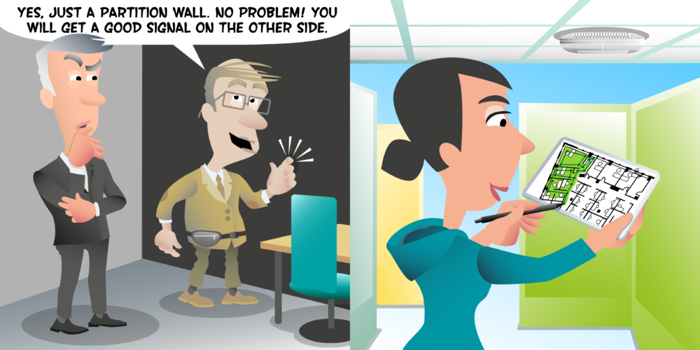
Hello. In this video we’re going to look at how we measure the attenuation of a wall, and we’re going to try and measure the attenuation of this wall here just behind me. So what do we need to measure the attenuation of a wall? Well, we need two things. We need something which can generate a wifi signal and we need something which can measure a wifi signal. Now what you use to for these two things can vary. There’s very many different approaches. For something that generates a wifi signal, you could go as far as using what we call an AP on a stick. That could be, for example, I have here a missed access point on a tripod connected to a POE battery. This could generate me a wifi signal.
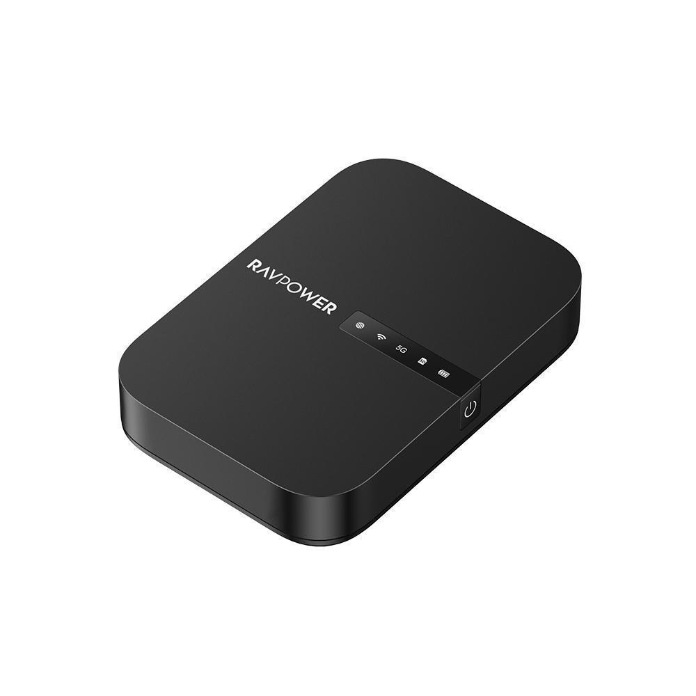
And a set up line is very good for when we’re validating our designs. And I use it quite often, but if all I want to do is measure the attenuation of a wall, it’s a little bit big to carry around. So an alternative approach would be just to get something which can be light, easy to carry around, battery powered, which generates a wifi signal. I’m using a little RAVPower file sharing device here, which has a built-in 2.4 and five gig access point. So it’s just a simple, cheap wifi device that runs on battery powered.
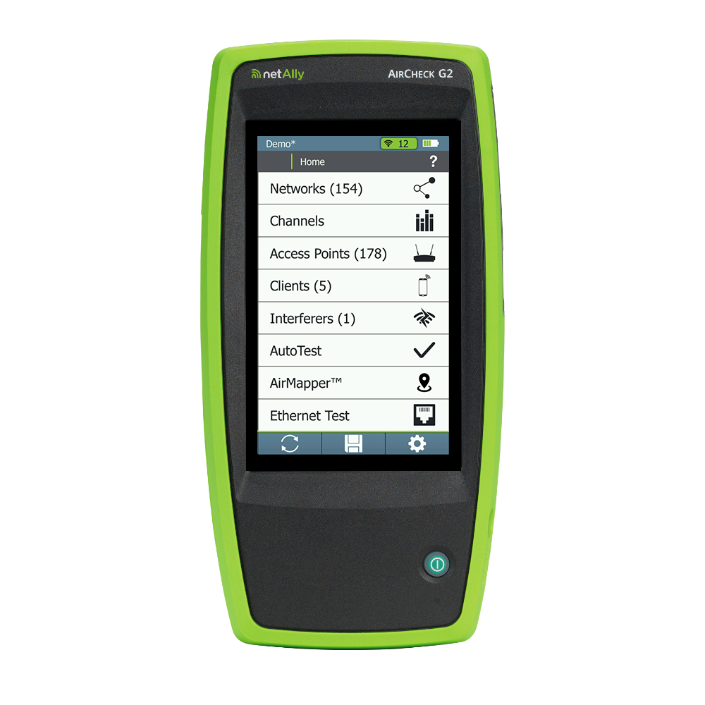
So that’s something to generate a wifi signal. What about to measure it? Well, again, probably my preferred device is the AirCheck, the G2 by NetAlly. This advice is a wifi test tool, but it’s again, it’s portable, it’s handheld, and I can carry it around very easily. But again, it could be any device that’s capable of measuring a wifi signal. It could be a laptop, it could be some sort of survey adapter. It could even be a mobile phone if you’ve got some sort of wifi monitoring app on your mobile phone. One nice thing I like about a G2 compared to using a mobile phone, mobile phone tend to scan all the channels. So if you’re measuring a signal, you’ve got to wait for it to get onto the channel that your export access point is running on, whereas this, I can configure it just to look at signals from this one device.
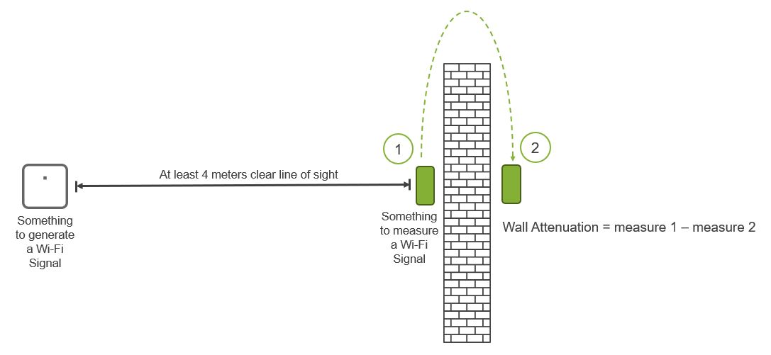
So that’s what you need something to generate an air signal, something to measure it. So how do we go about doing it? Well, you take the device that’s going to generate you a wifi signal and you want to place it between four to five meters away from the wall you are measuring. The reason we replace our device, which generates a wifi signal four to five meters away from the wall, is due to something called free space path lots, which is the rate at richer signal loses power as it leaves an access point. We can see that hereby its green line on its graphic. You can see just how quickly the power is lost as it first leaves the AP, in fact, over the first meter is where we lose most of our power. You can see this here on its diagram and we’ve got a five gigahertz radio transmit at 14 dBm, that’s positive 14 dBm.
And by the time we get to one meter ray, it’s that minus 33 dBm. That is a massive 47 dB of lots just over the first meter. But when we move from one meter to two meters, we lose another 60 B. And in fact, every time we double the distance, so from two to four meters, it’s another 60 B of loss. So as we get further away from the AP, the rate at which the signal and losing power goes down. So what does all of this have to do with measuring the wall attenuation? Well, if we put a wall into this graphic at about five meters away, you can see that as the signal hits the wall, there’s a lot of power and that is the amount of attenuation that occurs in this wall. And we want to measure that more on the flat part of this curve.
Then on the really steep part, because if the wall is near the AP, then we’re going to be measuring this steep drop off as well as the loss through the wall. So if it looked like this and we had our AP only one meter away from the wall, a lot of the loss we’d be measuring would actually be the free space path loss and not just the loss of the wall. So that is why we make sure that our access point or device that’s generating an air signal is at least four to five meters away from the wall. So we’re going to tell this device, so I’m going to put it about four or five meters away from this wall.
Perfect. Having done that, I’m going to configure my monitoring device to look for just that one device and I can see that here. And I am going to put this on a mode where it gives me a nice big signal strength, so I can read that very clearly. And then I’m going to make sure I’m stood with clear line upside between this device and the device I’m monitoring that’s about four to five meters away. It can be more than that, but a minimum of four to five meters. What I don’t want to do is stand in the way because now I’m measuring the loss of my body as well as what’s happening in the wall. So clean line of sight. I’m also taking note that of the orientation that my reading device is in and antenna orientation changes a signal reading. So if I’m going to hold it like this or like this, that’s going to change how it picks up the air signal.
So I want to make sure that both sides of the wall, my device is in the same orientation, clear line upside, correct orientation, and I’m going to take note of the air signal. In this example here, I’m reading about negative 45 dBm, and then I’m going to go to the other side of the wall. So now we’re the side of the wall. I’m going to take my device, same orientation as it was through the wall. Again, me standing to the side of the device not to attenuate a signal. And I’m going to look at the signal strength of my AP and I can see that it’s now about 40 minus 48 dBm. So it was one minus 45 on the other side. Now it’s minus 48, so we take minus 45 for 48 and we get about a three dB loss through this wall. And that’s it. That’s how we measure the attenuation of a wall.
Measuring Wall Attenuation
In the video Peter uses the following tools:
RAVPOWER FileHub
(Something to generate a Wi-Fi signal)
NetAlly AirCheck G2
(Something to measure a Wi-Fi signal)
Next Videos


