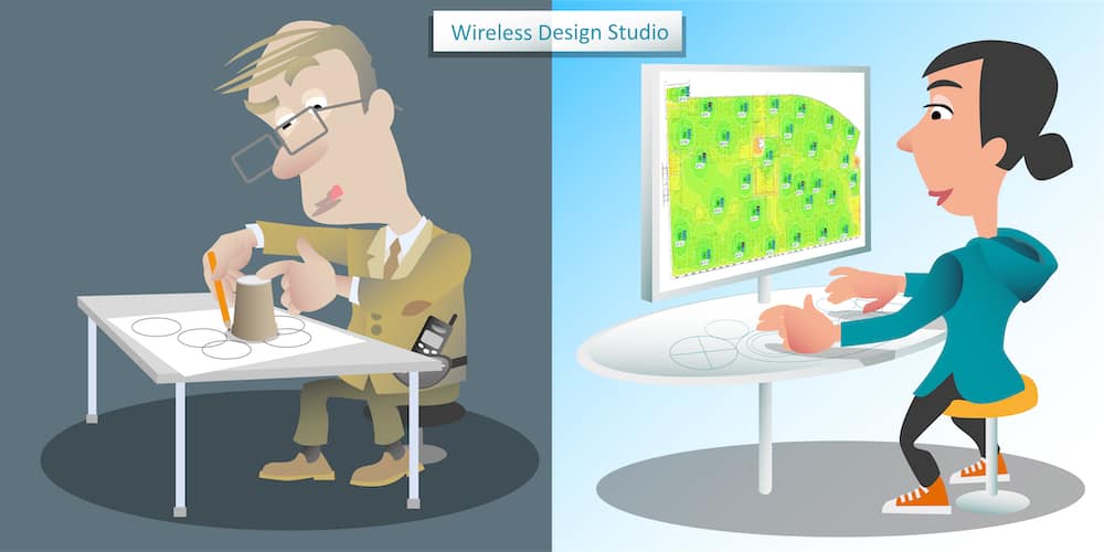
Hello. In this video we are going to start to look at the process of creating a voice grade wireless LAN design for an office environment using professional wireless LAN design software. Now, let me be clear wireless LAN design is not put in dots on the printed building plan and coloring it green.
Now, for this example we are going to carry on looking at the same example we looked at in the ARF design requirements video. You might remember that coverage was required everywhere except the closets, elevators, stairwells, and restrooms. Let’s remind ourselves of the design requirements for this office. Voice was a number one requirement with up to 60% of the office’s 70 employees on voice calls at the same time. Our recommended office voice grade wireless land requirements are primary signal strength of -65 dBm, secondary signal strength of -67 dBm with a signal-to-noise ratio greater than 25 dB. We are also going to design the corporate SSID to be five gigahertz only with no co-channel contention.
Let’s look at how to start to create an ARF model. Now, I’m going to be using the Ekahau design software. As you can see, I’ve already imported my building plan. Now, the first thing we need to do once importing our building plan is to scale the plan. I’m going to do that with my scale tool and I’m going to pick two poles from which I’ve already measured the length, which I’ve done already with a laser measure between this wall here and the door, all the way down this long corridor. That length was 36.3 meters. I’m going to type 33.6 meters and hit enter. Now that gives I plan scaled now.
If I was to add an access point to this plan, now… Let me select a Mist AP43 and we’ll put it somewhere in the middle. Brilliant. We can see that one AP fills the entire building. The problem is I may have imported a building plan and I may have scaled it, but I’ve not drawn on any walls yet, or any windows, or any door. I’ve not put in any objects, which are going to attenuate this ARF signal. As fair as the Ekahau software is concerned it’s showing me what this AP would look like if it’s in the middle of a field, in an open space.
Let me go ahead and delete that access point. The first thing you need to do is draw some walls. We can do that. We can draw some walls and you can see there’s lots of different walls here already built into the Ekahau2 as it is into lots of other wireless LAN design software. I’m going to pick one and I’m going to start drawing some walls. Now, if I draw, I’ve just picked a drywall, I’m going to pick and then I get to a door. Well, a little tip if the door’s the same attenuation value you can draw over it. If it’s not make sure you always click both sides of the door. Then that will give us the opportunity to come back later and change what the attenuation value is. I click both sides of the door and I come up here. I start drawing in all my walls. I’m not drawing them too neatly at the moment, because this is for an example, but we’re going to draw in my walls.
Now, the next thing I have to do is I may decide that… You can see the default value here is 3 dB, but maybe I’ve been on site and actually measured these walls and actually there were 4 dB. The next one I’m going to do is actually modify the attenuation to be the value I’ve actually measured. I’m going to put it in 4 dB and I’m going to hit enter on that. Now, I’ve changed these walls to four dB walls. What about the doorways though? The doorways, I’m going to select each doorway and the doorways are then going to change the wall type of them, because they’re actually going to be solid wooden doors here. With a 6 dB lot. I’ve now got 4 dB from my walls, 6 dB from my doors. The next thing would be to carry on through its entire plan drawing all the doors, windows, elevators, and making sure I’ve got the real measured attenuation values assigned.
Now, I have drawn all my walls. You’ll see that there’s different colors for different wall types. The dark green color here is an elevator wall, 30 dB watts. We’ve got a red color for brick walls with a 10 dB watts. The light brown color, which we sat to a 4 dB watts for the drywall and we’ve even got dark brown colors for the 6 dB solid wooden doors.
Once we’ve drawn all these walls and set all their attenuation values we can then start to model what the ARF coverage from an access point would look like. Let’s take a look at that now. If I was to look at the coverage of an AP43 you can now see how the different attenuation values effect the signal of this AP depending on where I put it. I can now move this around and have a look at what the coverage would be like in different locations and different areas of my building.
Now, once we’ve got this ARF model built with attenuation values added onto walls, and windows, and any object that’s going to attenuate my signal the next thing I may want to do is define areas where coverage is required. Again, most design software has some sort of area tool that they can use. I’m going to draw an area here round the outside of this building, which you’ll see me do here. I’ve just defined the area where I want coverage. You’ll see at the moment this is set to be Ekahau best practices. If you watch the gathering the ARF requirements video from the defined section of its website you’ll remember we defined the set of requirements for its office building. I’ve actually entered those requirements into this software and I have called it office requirements.
Here we go. We’ve got -65 primary signal, -67 secondary, 25 dB signal-to-noise ratio. I’m going to actually set this newly created area and I’m going to say it needs some meet off its requirements. However, you may remember from our requirements video that not all areas inside its office plan required wifi coverage. It was some exception areas closets, stairwells, restrooms, elevators. What we can do is we can actually exclude them from the area with an exclusion tool. Let’s have a look at doing that now. We have got a closet here we want to exclude. Then most of those areas around the building core, which is here. I can zoom in a bit just to help me click accurately as I draw around this area to be excluded. Now, as I do this notice I have still, although this doesn’t require coverage, accurately modeled this area. It is going to affect what the coverage looks like in other parts of the building. It’s good still that we’ve drawn all these walls in. We’re just going to exclude it from the area that’s required to have coverage. Now, we have it. There’s our exclusion areas drawn.
We are now ready, having created this ARF of model, to start placing our access points and designing a wireless network. We’ll be looking at how to design its plan for both primary and secondary coverage in somewhat newer videos. In the design section of this website.
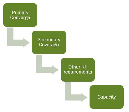
When we get to the stage of placing access points we are placing access points in order to meet our requirements. It’s helpful to consider the requirements in the following order. First, we’re going to place access points to meet our primary coverage goal. That is we are making sure we have enough access points to meet our minimum signal strength in all required areas.
Having done this, we will then add additional access points to meet our secondary coverage requirements. It might be that secondary coverage is only required in certain areas or only required over a certain percentage of the area. For example, we might decide we only require 90% of our area to meet our secondary coverage requirement. Now, this means we don’t need to worry about the corners and the edges of the building where it’s often hard to meet the minimum secondary coverage requirement.
Now, next we would assess our design against any other ARF requirements, such as signal-to-noise ratio and co-channel contention. Then make any necessary adjustments, which might be disabling 2.4 gigahertz radios or changing an access punch channel or transmit power. Remember that every time we adjust something like this in our design we then have to go back and check do we still meet our primary and secondary coverage requirements.
Only once all of these ARF requirements have been met is then we consider capacity. Do we have enough access points in each area for the number of users? Now, this may result in additional access points being placed into our design, but, again, every time we do this we need to make sure we’ve not broken one of our previous requirements. For example, adding access points for capacity may result in more co-channel contention.
Now, do watch the other videos in the design section of this website where I’ll be going through each of these design steps. Thank you for watching. Goodbye.


