#10 DESIGN
Design to meet the gathered and defined requirements
Hello and welcome to this video on the design phase of the wireless LAN design framework. So what is the design phase all about?
Well, when we create a wireless LAN design, the primary objective is to really design how many access points we need and where those access points locations should be. So ultimately the output from a wireless LAN design will detail all the access point locations , any antennas that’s going to be installed on them and their location and orientation. A wireless LAN design may also include coverage heat maps. It will probably include insulation and mountain details. It may also include some recommendations for the configuration of the wireless LAN.
This may include power and channel settings or RRM settings so that we can tune the system to automatically set the power and channel. So when we’re thinking about creating a wireless LAN design, the wireless LAN design engineer has many tools and methodologies available to them and there’s a number of different processes they could take to produce a wireless LAN design. But we’re going to try and guide you through a structured methodology for creating a wireless LAN design. Now, if we were going to talk about creating a wireless LAN design, we may come up with a very logical workflow which may look a little bit like the one on the slide here.
Whereas we’re going to start with what I would call a wireless LAN design workshop. Now this is really a meeting with the customer and the stakeholders of the wireless LAN to define and determined the requirements. Now, we’ve already talked about this phase. This is a defined phase, but I’m including it here because I want to see where it fits in our workflow for creating a wireless LAN design.
We’ll see why in a little bit of time. Now having defined all the requirements, the next sort of logical step will be to take some onsite measurements. We need to know what the attenuation is of the walls, of the windows, of the doors. We need to understand the RF characteristics of the building. We’ll also want to take a scale measurement from the building. We want to know the size of the building so that when we are creating an RF model we can scale our plans. We may also want to note mountain locations and say, “If we’re in an atrium area, where could we actually mount access points?” So there’s lots of onsite sort of measurements and data I’m going to want to collect. And we’ll then probably move into some sort of RF modeling. Now that RF modeling may well be done in some sort of wireless LAN design software. And we’re going to look through how we do that RF modeling piece later on in this video series.
Following creating an RF model, we may want to validate that RF model. So that would mean going back onsite, maybe putting up some access points on tripods in the locations that we’ve placed them in our RF model and check then that we get the coverage we have modeled. Having validated the RF model, we’ll make any final adjustments to our design and we come up with our final wireless LAN design. And then the final part will be some design documentation detailing the AP locations, the mountain of those APs, and possibly some coverage heat maps as well.
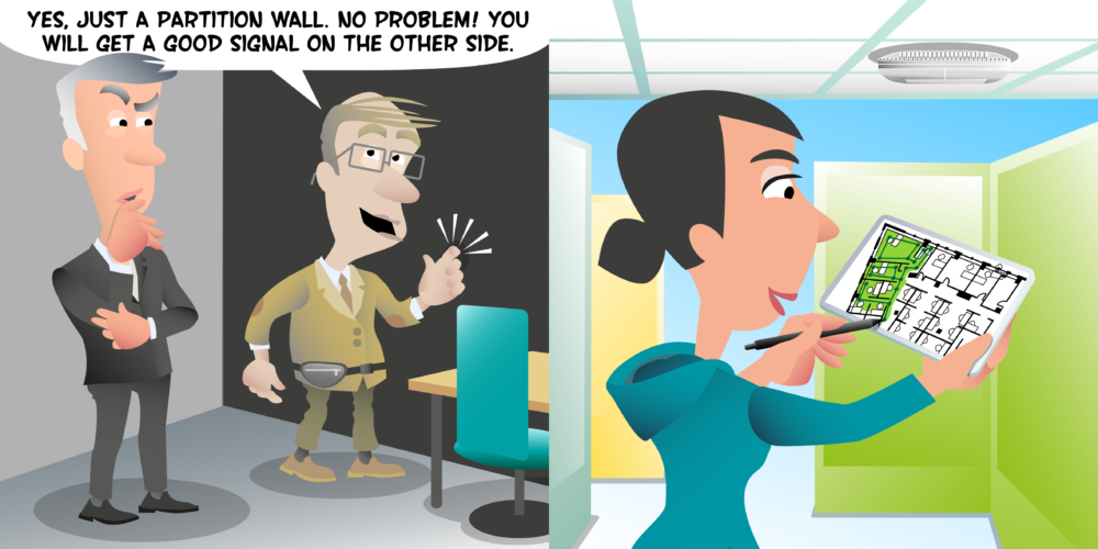
Now that sounds a very good and logical workflow for producing an RF design. Though, the only issue of this is it’s not always practical to carry out all these steps in the order I’ve detailed. Let’s just have a look at how we might go about doing this. Well, two of these steps, which we’ve got doing onsite measurements and validating the RF model, both of those elements you’re going to need to be onsite for, whereas these elements could potentially be done remotely or offsite. So if we are thinking of number of times we need to visit the site we’re doing a RF design for, we’ve at least gone on at least two trips. The defined stage may also be onsite. You may go and have an onsite customer meeting, which could be potentially another visit.
And sometimes practically we don’t have time to visit a site multiple times when producing an RF design. It may be down to physical distance, it may be down to budget, time scales. There could be a number of reasons preventing us from doing that. So while I think this represents a very good logical workflow, sometimes these steps need to be rearranged a little bit. So let’s look at maybe a more practical workflow. Now, if we wanted to put those two onsite visits into one visit. So we want to get down from two visits to one visit, it might be that we do a design workshop. Now at the moment I’m assuming that’s remote, so I’m assuming we can have maybe a conference call with the customer. We’ll look at that that’s not possible in a minute. Then we are going to do a predictive RF modeling.
So we’re going to move the RF modeling into the next phase. Now we’re going to need to take a lot of CAD work in this. We’ve not been on site, we’ve not taken any measurements yet. So we’re going to, from the building plans, maybe from CAD diagrams and from information we can get from the plans, we’re going to take a guess at the wall attenuation measurements and we’re going to rough up a rough design just to give us an idea of where we might place access points. Again, we’ve not been onsite so we can look if we can physically mount them in this location. But we’re going to do a best guess design.
And then we’re going to do our onsite visit. And during that onsite visit we can walk around, we can look at where we… if there’s any of those locations where we couldn’t mount APs, we’re going to take some onsite measurements. We’re going to measure the wall and we’re going to, very often I’ll do this while onsite, I’ll update my plan with the correct values I’ve just measured. I can also validate my RF model at this stage. I can start to put some AP on the stick measurements and check that my model meets what I’m measuring onsite. So I’m putting all the onsite bits together. It means that leaving that site I have a validated RF model and then I can do any final designs. And if I move APs around in my final design phase, I know it’s still going to meet the requirements and meet the building because I’ve validated the RF model while onsite.
Following that, I can go to producing my design documentation. But what if we actually need to have our design workshop onsite as well? Well, that would mean yet another onsite visit. So is it actually another workflow where we can still do one visit onsiteand put all our onsite bits into one section? Well, again and again, this is just another example of how we may do it. We could move the predictive RF model into the very first phase. So we have a conversation with the customer, they give us their building plans and we don’t know what the requirements are exactly yet. We’ve maybe talked very roughly. But what we’re going to do is tailor those building plans and try and create a rough model of the building. Again, we’re going to guess the wall attenuations and we’re going to start placing some APs on just so we’ve got a rough idea of what the RF environment looks like. Now we don’t know everywhere they want coverage at this stage. We don’t know all the requirements, but we’ve got a rough model of the building.
And then what we can do is we can go onsite. First thing we might do is have our design workshop where we go through the plans, we go through the areas, we go through their requirements. Following that meeting, we may walk around the building, measure some wall attenuations, look at all the different places, again, chat to the customer in more detail about what they require as we’re moving around the building. And then from that, we can update our model, which is all prepared with the correct onsite measurements and we can take some access point on a stick measurements to validate the RF model. Now it might be at this stage you don’t really know because you’ve only just got the requirements exactly what the locations are going to be for those APs. You’ve not done the design yet. So how can you do proper AP on a stick measurements?
Well the key and important thing to understand at this stage is we’re not going to validate the final AP positions. We’re just validating the model. So provide I put an access point up on a stick and take some real measurements of it and then I place an AP in that same location in my model and see if I get the same coverage. And I do that in a number of locations just to spot check my model. If my model is accurate to those locations as AP on stick measurements, I can then move to my final design and I can put the APs in different locations because I’ve already validated that my wall attenuation measurements are correct with my validation measurements.
So what we’re looking at here is we’re just looking at three driven workflows we could do. The important thing is we’ve got all these stats in and yet we can do them in different orders and we can have different approaches to doing wireless LAN design. But the important thing is that we’re going through a structured workflow and we’re getting to a final design which has been validated which is used in real world measurements. Now, if we were asked to a wireless LAN design for a building that doesn’t exist yet, so we couldn’t go onsite and do any RF measurements or any validation, then we would be creating a pure predicted design. And that would have to come with all the caveats around the inaccuracies of doing a pure predictive design. And some things may have to be corrected when we do the validation survey at the end of the deploy phase.
So one of the key elements to wireless LAN design is RF modeling. We have it in all of our phases. Sometimes we’re doing predictive modeling, sometimes we’re doing modeling based upon real values. And then we’ve also got the final design phase as well where we’re doing further sort of AP placements within that model. So what’s the sort of process for doing RF modeling? Well, the actual methodology you’re going to use will depend a little bit on what design software and RF modeling software you are using. But most of the enterprise class wireless LAN modeling software follows the same sort of workflow. You’re going to need to import some building plans into the software. Having imported the building plans, one of the first things you’re going to do is scale those plans and having an accurate scale is incredibly important.
And some people I’ve seen have scaled it just to a doorway to say, “Well a doorway, what is it? It’s about, I don’t know, three feet.” The problem is what if it’s not three feet? If you are off by just 10 centimeters in a doorway, then that could end up being your whole building is off by about five meters when you look at the entire building. Even if you’ve measured a doorway, how accurate are you clicking from one side up the doorway to the other inside a software?
Again, if you are off by just a few centimeters, that could be several meters over the entire building. So I always advise when we’re talking about scaling a floor plan, we want to take the longest measurement we can. So when generally in like office buildings, I’ll often look for long corridors and take a laser measure down the entire corridor. If I’m in a warehouse, I look for long aisles and take a measurement down the aisle, but I’m looking for the longest measurement I can get within the building to try and scale the plan to. Now it is possible to scale a plan from Google Earth or Google Maps where you can look at the outside of a building, but just bear in mind that if you doing the outside, you’re doing the external walls, not necessarily the internal measurement.
And you’ve got to… I would only do that if I can’t visit a site, if there’s some reason that I can’t physically get a real measurement because you may well be off about up to about two meters from measuring on Google Earth. So it might be good for that initial predictive model before you visited the site. But while I’m onsite, I’m always going to try and take a real measurement inside the building as long as possible.
Now if we’re designing a multi-floor building, we’re going to need to put in multiple floor plans, scale each off the floor plan, and then we probably need to align the floors as well. Aligning the floors just means that our RF modeling software can model the signal penetrating our floors. Having aligned the floors, we then need to assign attenuation values to objects like walls, windows, doors. Depending on the software you’ll using, there’ll be a number of ways of doing it and it may be as simple as you draw in over the walls and the doors and the windows and assigning a material to them and attenuation value to that material. If you’re working with AutoCAD files, some RF modeling software allows you to import the layers from the AutoCAD and assign attenuation values directly to those layers.
We will also need to be careful to make sure we’ve got the right height of the building defined. And if walls are not full height, we’ve defined the right height of the walls as well. Very often inside our design software, we can then also define what we would class as requirements areas. These are areas where we know we need wifi coverage, but we also know what the requirements are for that area. So we know how much primary signals from secondary co-channel interface, we know the capacity in that area.
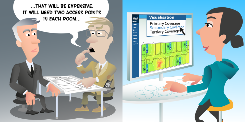
By doing that, our RF modeling software can inform us where if we’ve met the requirements once we’ve done our design or wherever we are still failing those requirements. So we may want to define those areas and we’re then going to go to placing access points during the design itself. We’re going to place access points until we’ve met all our RF requirements. And that’s probably going to be a bit of a iterative process. We might place access points to make sure we’ve got prime coverage, and then we look at secondary coverage that may need a few additional access points. And then what about capacity requirements?
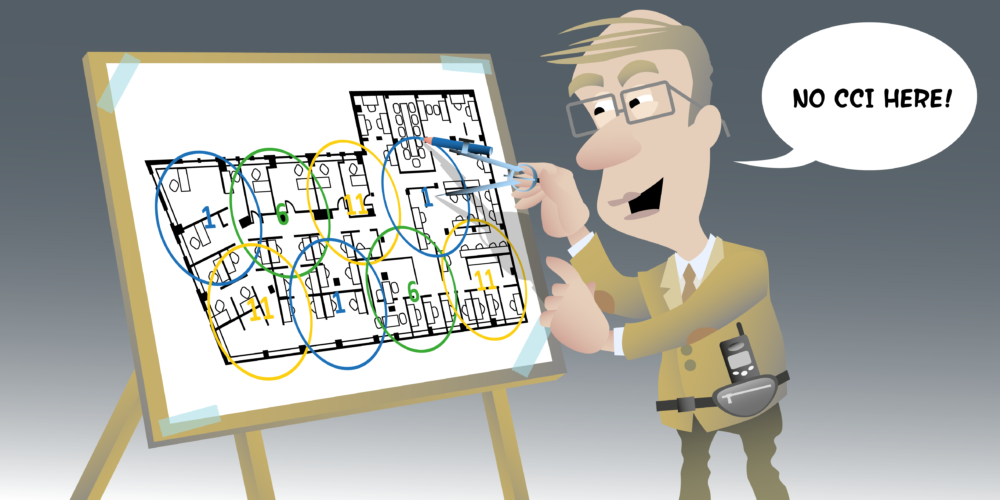
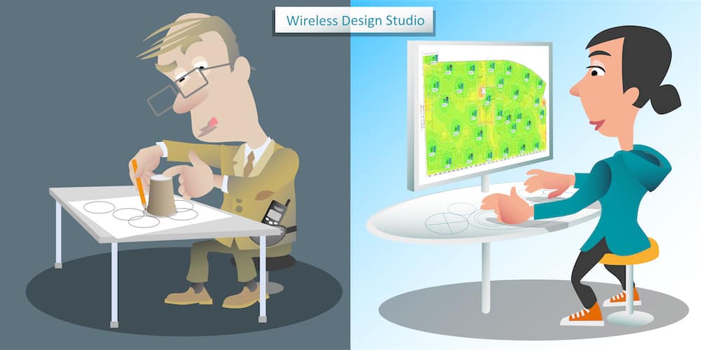
And all the time we will be looking at things like our signal-to-noise ratio. We’re going to be looking at our co-channel interference and making sure we still meet those requirements too. Having placed all the APs, it might be we are going to create a channel plan and also consider power levels as well of the access points. So that is our sort of overview of our RF modeling process. So let’s have a look at how we do some updates inside some RF modeling software. When designing wifi, it’s important we use professional wireless LAN design software. So don’t be like Stanley here drawing around his coffee cup in an attempt to estimate the coverage from one access point. You see, even in open space, the coverage from an access point is never going to be a perfect circle. And even if it was, won’t be the chance it happened to be the size of your coffee cup.
Come on Stanley. I think you can do better than that. Misty, on the other hand, is using professional wireless LAN design software and it is important when choosing the software that we pick software which can model the coverage from the missed access point we’ll actually be installing. So do you please watch the other videos in this design section of the website while I’ll be guiding us through the process of using the design software to create a wireless LAN design. Now, the final phase of wireless LAN design is documentation. And this documentation could take many forms from a single design report or it might be split into a set of documents. For example, you might have a document which details are designed, an insulation guide to bill off materials, may be a project plan, but however you deliver your documentation, either a single document or many documents, at the very least, your design documentation will include details on the number of access posts and antennas and their location.
Now it should also include detailed instructions on AP and antenna insulation. That might include pictures of where the access points and antennas are going to be installed, what brackets to use, what height, what orientation. You see, the more detail you put into this documentation, the less likely insulation errors will be made. Maybe we’ll even include instructions on what to do if for some reason an access point can be placed in the desire location. Ideally, you want the installers to come back to you, the design engineer with any corrections, not just make a decision themselves as to where the AP should be moved to.
Now this design documentation will also typically include heat maps, which might show prime coverage, secondary coverage, signal-to-noise ratio, maybe even channel overlap heat maps. But when choosing which heat map to include in the design documentation, it’s important to consider who is a reader at a technical. If not, you might just confuse them by having pages and pages of heat maps. So maybe you’re going to end up creating a technical report and then maybe a high level business report as well. And finally, something to consider in the documentation depending upon the project requirements, is you might want to include a bill of materials. So thank you for watching this video on the design phase of the wireless LAN framework. Goodbye for now.
#11 Wall Attenuation Measurements
Measuring Wall Attenuation In the video Peter uses the following tools: RAVPOWER FileHub (Something to generate a [...]
#12 Access Point on Stick (APoS)
Mist APoS configuration When pre-staging your APoS configuration, don't forget to enable "AP Config Persistence" in the site settings [...]
#13 Voice and Video Office Design
Voice and Video Design Minimum Primary Signal -65dBm Minimum Secondary Signal -67dBm Signal-to-Noise (SNR) 25dB [...]
#14 Primary Coverage
Primary coverage is the signal strength from the access point with the strongest signal. The primary coverage requirement will [...]
#15 Secondary Coverage
Secondary coverage is the signal strength from the access point with the second strongest signal. The secondary coverage requirement [...]
#16 SNR & Co-Channel Contention
Signal-to-Noise (SNR) Signal-to-noise (SNR) compares the level of the received signal to the level of background noise and specifies [...]
#17 VoIP Office Capacity
VoIP Capacity Requirements VoIP capacity requirements are normally dictated by the number of simultaneous VoIP calls per AP radio. [...]
#18 Hospitality
Hotel and Dormitory Design Minimum Primary Signal -65dBm Signal-to-Noise (SNR) 25dB AP Placement Inside rooms/dormitories [...]
#19 Antennas
Number one antenna Rule: Cover what you want and not what you don't want Lamp post example: [...]
#20 Warehouse
Warehouse Design Minimum Primary Signal -67dBm Minimum Secondary Signal -70dBm Signal-to-Noise (SNR) 25dB Frequency Dedicated [...]


