How do we design wifi for the 6 GHz band? Well, in one sense, the introduction of the 6 GHz Frequency Band does not really change how we design wifi. We still have the same design methodologies and tools available to us, predictive designs, AP on a stick measurements, et cetera.
But now we just have to model, not only the 2.4 GHz Band and 5 GHz Band, but also the 6 GHz band as well. And we’ll want to ensure all the same types of requirements are met. Primary coverage, secondary coverage, signal-to-noise ratio, channel interference.
However, there are some additional considerations with the 6 GHz band. And one of these considerations are the measures in place to protect incumbents.
Now, sharing a frequency band with incumbents is no new concept to the wireless land industry. We share sections of the 5 GHz band with radar systems, and redeploy dynamic frequency selection and transmit power control measures to ensure we don’t cause undue interference. Well in 6 GHz band we also have a set of measures in place to make sure we play well with the incumbents in the band.
So first of all, who are these incumbents? Well, there’s three main incumbents in the 6 Gigahertz band. We have fixed service microwave links, both pointer point and pointer multi-point links. And then we have fixed and mobile earth to space satellite links. And finally we have television broadcast services, think TV truck with amast.
Now the table here shows which UNII bands in the US these incumbents operate in. And in order to protect against these incumbents, a number of device classifications have been defined each with our own set of rules, and we have both AP and client device classifications.
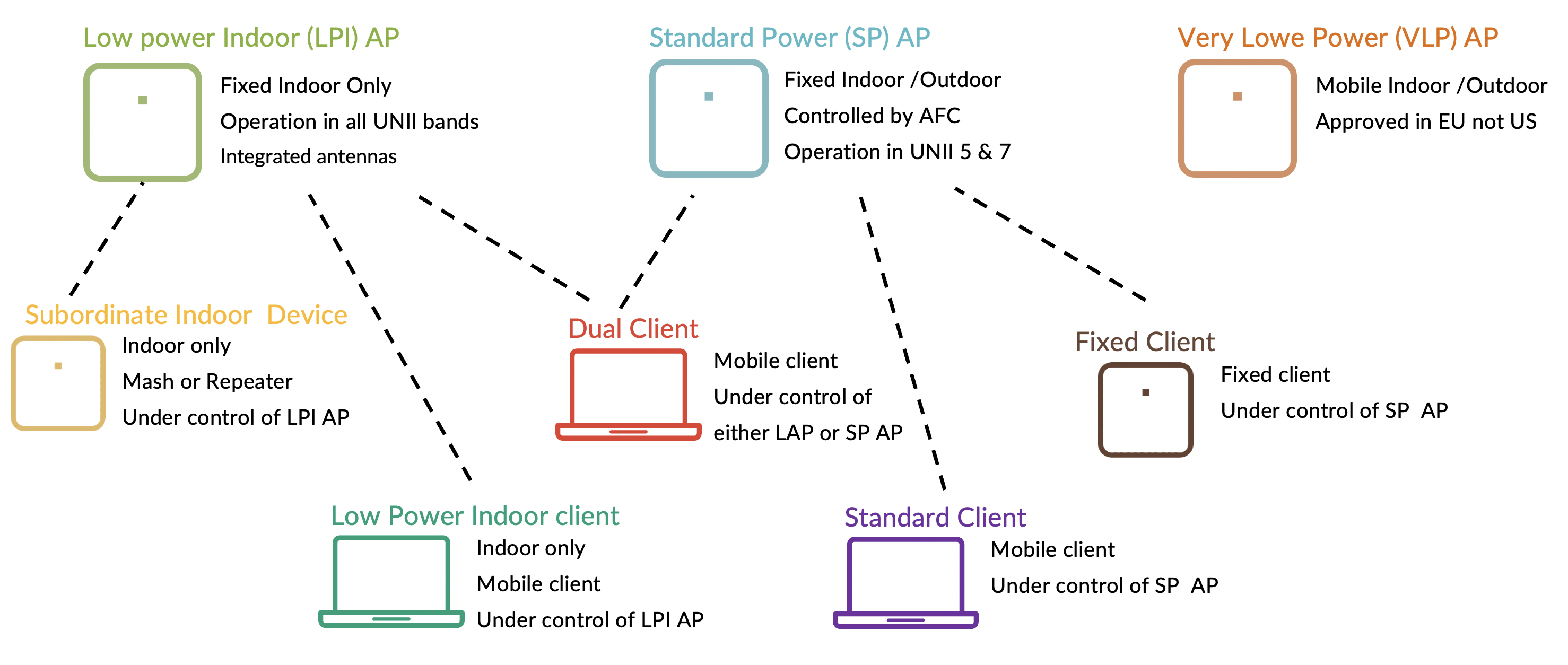
So let’s start by looking at the AP classifications. We have three classifications of 6 Gigahertz access points. Low power, indoor access points, standard power access points, and very low power access points.
First, let’s talk about the low power indoor access points. As the name suggests, these are to be used indoor only and in fixed locations. The assumption here is that all the incumbents in the 6 Gigahertz band, our outdoor systems, and therefore indoor access points with restricted transmit power will not cause interference.
Because of this, low power indoor access points can operate across the whole 6 Gigahertz band. So in North America that would be the whole of the 1.2 Gigahertz of available spectrum, comprising of regulatory bends, UNII 5, 6, 7, and 8. In Europe, that would be the first 480 megahertz of 6 Gigahertz spectrum.
Now the main restrictions to indoor low power access points and that they must be used in fixed locations. They have limited transmit power and they also must have integrated antennas. Now the maximum transmit power of low power indoor access points is set by regional regulators.
So in the US, the transmit power is limited by what we call power spectral density, rather than EIRP. With power spectral density, the density of power decreases as you increase channel bandwidth. So an 80 megahertz channel would allow for higher maximum EIRP, then a 20 megahertz or 40 megahertz channel.
The maximum transmit power in the US for low power indoor access points is limited to five dBm per megahertz. This results in the following EIRP limits — 18 dBm for 20 megahertz channels, 21 dBm for 40 megahertz channels, 24 dBm in an 80 megahertz channel and 27 dBm for 160 megahertz wide channels.
This plus 3DB power increase we get every time we bond to channels together offsets the increase in additional noise we get when using wider channels. You see, every time we bond two channels together we get 3DB increase in the noise that’s actually twice as much noise.
So unlike in the 5 Gigahertz band when we have a constant ERP, our signal-to-noise ratio is therefore reduced by 3 DB every time we bond channels. However, in the 6 Gigahertz band using power spectral density, we can theoretically keep a constant signal-to-noise ratio if we are using the maximum transmit power possible.
However, access points are rarely configured for max transmit power and therefore we are more likely to actually see the same signal-to-noise ratio reductions when channel bonding in 6 Gigahertz as we do in 5 Gigahertz.
Let’s take a look at a couple of examples. If an axis point was configured with a transmit power of 21 dBm, then it would use the regulatory maximum transmit power of 18 dBm when using a 20 megahertz wide channel, but it would use the configured 21 dBm when using a 40 megahertz channel.
Well, as the AP is configured for 21 dBm, it would continue to use 21 dBm for 80 megahertz wide and 160 megahertz wide channels, and therefore you would see the same reduction in signal-to-noise ratio for the 80 and 160 megahertz channels as we do when using 5 Gigahertz.
Let’s look at another example. Let’s say we configured an access posts transmit power for 15 dBm. In this case, 15 dBm would be the transmit power used for all bands and therefore the impact of channel bonding on signal-to-noise ratio is still something you are going to need to consider in your designs.
Now many regulators in other countries specify the max transmit power for low power indoor access points using EIRP. In the EU, for example, low power indoor access points have a maximum EIRP of 200 milliwatts, that’s 23 dBm. Whereas in the UK and Australia we have a maximum EIRP for low power indoor access points of 250 milliwatts. That’s 24 dBm.
The AP45 and 43 from Juniper mixed are two examples of low power indoor access points. The flagship AP45 has three four by four radios for wireless land access, and a dedicated fourth radio for wireless land monitoring, as well as an integrated mixed BLE antennae array for location based services.
Whereas the AP 34 has three 2×2 wireless land access radios and a dedicated fourth radio for wireless’s land monitoring. Now one of the measures taken to ensure that low power indoor access points do not interfere with incumbents in the 6 Gigahertz band is that only integrated antennas are allowed.
And this is to discourage these access posts, although antennas been installed outdoors. Now while indoor access posts with integrated omni antennas make sense for carpeted office environments, not all indoor environments are suited to the traditional integrated antennas built into most enterprise class access points.
For example, take a warehouse environment with high racking where directional antennas would be much better. Now Juniper Mist have taken an industry-leading approach to this problem by getting a number of a cell tax external antennas certified with the AP 45 E access point.
These antennas have a proprietary one-time connection mechanism where the antenna connections are sealed inside the access point housing at insulation time and the access point and antenna become a single integrated solution.
Here is the Accel Tech warehouse antenna, specifically designed for the AP45 E. As you can see, this is a 10 lead antenna with two proprietary connectors, one slightly bigger than the other.
Now these two connectors connect up to the AP45 E. We can see here on its AP45 E, it has a connection on this side and it also has another connector on this side.
So what you do is, let me just take one of these connections. I’m going to take the larger up to two connectors and snap it into place. There we go. It’s now connected up to the AP and you can see once it’s snapped in place, you can’t pull it out, it’s locked in position.
And then what you would do is you would take one of the little covers, these plastic covers come with the AP, they’re just screwed on, and you would connect that over the antenna connector and it glues and attaches with security keys to lock it in position.
And therefore you now have a one integrated AP and antenna solution. Now at the time of recording this video, the AP45 E and a cell tech innovative solution has been approved for use in a number of countries around the globe, but it is still waiting approval in many other countries.
So make sure you check the up-to-date status of your own regulatory domain. The next category of 6 Gigahertz access point is standard power. Standard power access points still need to be installed in a fixed location, but the big advantage of standard power access points is that they can be used both indoor and outdoor.
However, standard power access points will be controlled by an AFC, that is an automated frequency coordination system, to ensure that they do not interfere with incumbents in the 6 Gigahertz band.
Standard power access points will be required to provide their location to a centralized automated frequency coordination system, which in turn will provide a frequency or channel which the system can use without causing interference.
The access point’s location will likely be obtained from a built-in GPS receiver. Now the FCC have approved the use of standard power access points in the US and have already conditionally approved several AFCs, but as of January, 2023, standard power devices are not approved in Europe.
Now even with an AFC, the FCC have only approved the use of standard power access points in UNII-6 and UNII-8 to ensure that they don’t interfere with fixed micro microwave links operating in UNII-5 and 7. And as well as being capable of outdoor operation, standard power access points have also allowed higher transmit power than low power indoor access points with a maximum EIRP of 36 dBm.
Not a final access point device classification is very low power access points. These access points can be installed indoor and outdoor, and they’re the only access point device classification, which can be mobile, so could be installed in public transport such as buses and trains. Now at the time of recording this video, very low power devices have not been approved in the us but have been in Europe.
And this results in two important design considerations. First in the US for now, 6 Gigahertz access points may only be installed in fixed locations and therefore 6 Gigahertz is not a suitable technology to provide wireless land access on transport systems.
However, in Europe, very low power is currently the only method of providing outdoor 6 Gigahertz access. However, as the name suggests, very low power access points are heavily restricted on transmit power with a maximum EIRP of just 14 dBm, that’s 25 milliwatts. And therefore, when designing outdoor 6 Gigahertz areas in Europe will probably require more access bonus than we would for a traditional 2.4 or 5 gigahertz design.
Now, as well as access point classifications, we also have client classifications. A very low power indoor client will connect to a low power indoor access point, and these clients remain under the control of the low power indoor access point.
In countries such as the US and Brazil clients also have their own transmit power limitations specified as one dBm per power spectral density. This results in 60B max per transmit power than the low power indoor access points.
In Europe, however, clients transmit power limitations at a same as the access points. The next client classification is standard clients, and these come under control of standard power access points and have a maximum transmit power of 17 dBm in the United States.
In the US client devices can be certified as either low power indoor clients or standard client or June clients. June clients have the advantage that they will be able to connect to either low power indoor access points or standard power access points.
However, it should be noted that many of the early 6 Gigahertz clients have only been certified as low power indoor clients and therefore once standard power access points are deployed, these clients will not be able to connect. And therefore until these client compatibility issues are straightened out, the deployment of a good reliable 2.4 and 5 Gigahertz network in these areas will remain important.
Now finally, in this video I want to discuss the difference in signal strength we might see in our designs and validation surveys. From a free space path lots perspective, there should only really be about one to two B difference between 5 gigahertz and 6 Gigahertz. We will also see a difference between 5 gigahertz and 6 Gigahertz in how they attenuate from different materials.
Now the images you see here show the difference in predictive coverage from both Ekahau AI Pro and Hamina planner. And while these do not show a big difference, they’re only showing downstream coverage. And a bigger difference might be seen from a client perspective, given the limitations in client transmit power.
These differences mean that it is likely 6 Gigahertz designs will require a slightly higher density of excess points and therefore a proper 6 Gigahertz design will be required, and we will not just be able to rely on our existing 5 gigahertz designs or deploy a rip and replace methodology.
So thank you for watching and I’ll see you next time.
Wi-Fi 6E Device Classification:


Next Videos
 #9 Wi-Fi 6E Define


